Blurry Print Edges in Digital Textile Printing: Causes
Blurry edges in digital textile printing usually come from one of four places: the artwork was rasterized poorly, ink drops landed in the wrong position, the fabric moved, or the ink spread after landing. The edge itself shows which family to investigate. A stair-step, double image, fuzzy halo, and yarn-following feather are different defects and should not receive the same fix.
Do not begin by increasing resolution, slowing every job, or changing the color profile. First print a controlled edge target on the affected fabric and read the shape. That test prevents one subsystem from being adjusted to compensate for a fault in another.
Read the edge signature first
| What the edge looks like | Most useful first check |
|---|---|
| Square stair-steps on diagonals or curves | Artwork size, raster resolution, scaling, and RIP interpolation |
| Two clean edges offset from each other | Bidirectional alignment, carriage reference, or fabric movement |
| A soft halo spreading equally from the boundary | Ink laydown, pretreatment, absorbency, and drying |
| Feathering that follows individual yarns | Surface hair, capillary wicking, and pretreatment coverage |
| Sharp in light areas but soft in heavy coverage | Channel limit, wet-on-wet interaction, and drying capacity |
| Sharp before fixation but blurred after it | Steam, heat, moisture, wash, or handling in the finishing stage |
| Defect appears only in one zone across the width | Nozzle condition, head alignment, fabric height, or local pretreatment |
| Edge shifts at a repeating feed interval | Feed calibration, roller contamination, tension, or encoder reference |
This table narrows the investigation; it does not prove a component is faulty. Change one controlled variable, print the same target, and compare it with the baseline before making the next change.
Start with a test file that can reveal the cause
A photograph is a poor edge diagnostic because the source may already contain anti-aliasing, compression, depth-of-field blur, or soft transitions. Build a small production target containing:
- thin positive lines and thin reversed lines;
- small text with horizontal, vertical, diagonal, and curved strokes;
- a hard boundary between a solid color and unprinted fabric;
- registration crosses or nested outlines in more than one channel;
- the same motif at its intended size and at a larger reference size;
- both low-coverage and high-coverage versions of the same edge.
Print the target through the normal RIP, profile, fabric preparation, and finishing route. Keep the file unchanged while testing. If every operator uses a different graphic, changes in the defect cannot be compared.
Rule out artwork and RIP softening
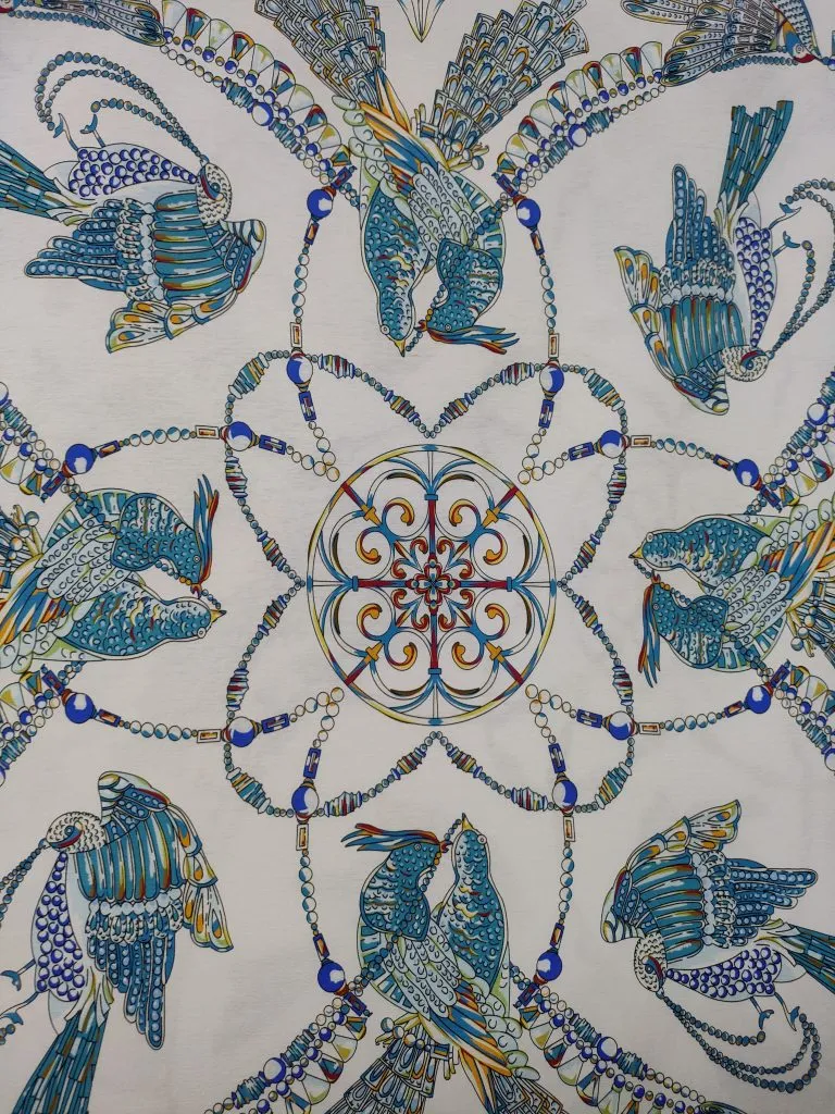
Open the production file at final output size. Vector paths should remain vectors until the RIP converts them. Raster artwork must contain enough real detail for that size; enlarging a small image only creates more pixels between the original ones.
Look for these file-side causes:
- the artwork was scaled after rasterization;
- a low-quality preview or compressed export became the production file;
- a clipping mask, transparency, or effect was flattened at the wrong scale;
- a contour, choke, or underbase setting extends beyond the color edge;
- sharpening or anti-aliasing differs between the design application and RIP;
- the RIP is using an unexpected input resolution or interpolation method.
Compare the RIP preview with the source at final size. If the stair-step or soft boundary is already present there, printer maintenance will not remove it. Fix the asset or export path and rerun the same target.
Separate nozzle loss from drop-placement error
A nozzle check comes before an edge test. Missing or deflecting nozzles can remove parts of a line, create a ragged boundary, or change one channel more than another. Recover to the documented nozzle baseline before judging sharpness.
When the nozzle pattern is complete but a test shows two offset edges, compare unidirectional and bidirectional output using the approved service procedure. If one direction is sharp and the combined directions are doubled, the bidirectional relationship or carriage reference is a stronger lead than fabric absorbency.
Also inspect whether the offset changes across the carriage travel. A fixed offset everywhere suggests a calibration relationship. A defect tied to one position can point to an encoder reference, guide contamination, local fabric height, or a head-to-head relationship. Do not change mechanical calibration without the equipment procedure and a reference record.
Check fabric movement and print gap
The print file assumes the textile remains flat and advances by the commanded distance. Stretch, skew, loose winding, unstable tension, a raised seam, or fabric lifting from the platen changes where the next drop lands.
Mark registration crosses along the length and across the width. Then ask:
- Does the error grow in the feed direction?
- Does it reverse when tension changes?
- Is one edge of the roll different from the other?
- Does the defect begin after a seam, wrinkle, or roll splice?
- Does a heavy ink area make the fabric cockle or lift?
- Does the same target stay sharp on a stable reference material?
Head height and print gap matter because a drop travels through moving air before reaching the textile. A larger or changing gap gives motion and static more opportunity to displace it. Use the lowest safe, documented configuration for the actual fabric; never trade head-strike risk for a sharper sample.
Fabric surface controls the final boundary
Textile is not a sealed sheet. Yarns, pores, twist, pile, finish, moisture, and surface hair form paths that can pull liquid away from the intended boundary. Two rolls with the same fiber label can therefore print different edges.
Inspect the surface under consistent light and magnification. Feathering that follows yarns or fuzz is different from a mechanically doubled line. Compare a known-good roll, and record the supplier, construction, finish, side, and lot rather than describing both materials only as cotton or polyester.
Pretreatment or sizing should hold the ink where the process expects it while remaining compatible with fixation and hand. Too little, too much, or uneven application can each change the edge. Check coat weight and uniformity through the approved process controls instead of correcting the symptom with more ink.
For a deeper explanation of this mechanism, see why fabric pretreatment affects pigment printing.
Match ink laydown to absorption and drying
An edge can be mechanically accurate at impact and then spread while the ink is still mobile. Heavy total laydown, a channel limit that is too high for the fabric, slow early drying, or wet-on-wet interaction can create a halo that is strongest around dark solids.
Use the same target to compare coverage levels. If light edges stay sharp and heavy edges spread, investigate ink limits, pretreatment, and drying before changing carriage alignment. Inspect the printed boundary immediately after printing and again after each finishing stage so the moment of change is known.
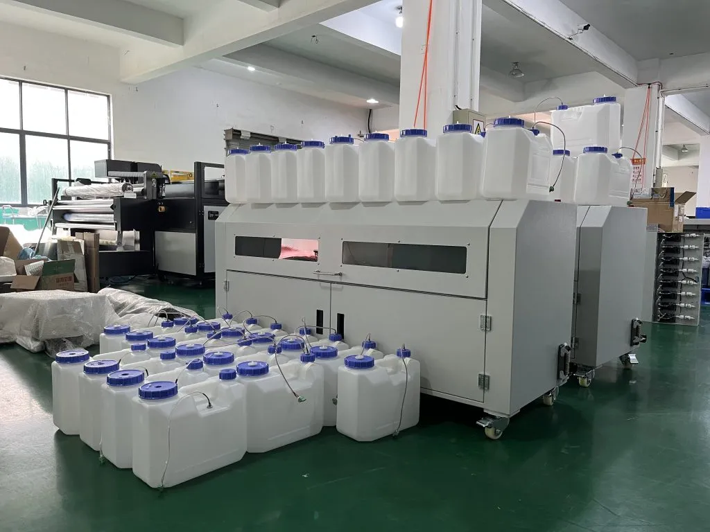
Do not adjust ink viscosity, dilute ink, add an unapproved fluid, or change heater limits outside the documented system. Ink delivery and drop formation depend on a formulated operating window. A blog cannot replace the ink and printhead technical data for that configuration.
Treat room conditions as evidence, not a universal setting
Temperature and humidity can affect textile moisture, static, ink behavior, drying, and machine recovery at the same time. The acceptable range is the one validated for the installed ink, head, fabric, and printer; do not copy a single range from an unrelated machine.
Record the room condition beside the edge sample. If a defect appears after a room change, acclimate the fabric and restore the documented operating state before editing the profile. Static-related displacement is more likely to move fine droplets or attract lint than to create the yarn-shaped halo of liquid wicking, so the visual signature still matters.
Compare the print before and after finishing
Fixation cannot sharpen a boundary that was already diffuse, but it can reveal or enlarge a problem. Steam, heat, moisture, washing, and physical handling can move unfixed color, distort the textile, or expose weak pretreatment.
Photograph or scan the same marked location:
- directly after printing;
- after drying or fixation;
- after any required wash and final drying;
- after the care test used for product approval.
If the boundary begins sharp and changes at one step, keep the printer settings stable and investigate that finishing step. If it is already soft at the first inspection, post-treatment is not the initiating cause.
Use an elimination order that changes one variable
Run the investigation in this sequence:
- File: confirm a known test target and final-size RIP preview.
- Nozzles: recover to the approved pattern.
- Placement: compare direction, alignment, and position across the width.
- Movement: inspect fabric flatness, gap, feed, tension, and registration.
- Surface: compare a known fabric and pretreatment uniformity.
- Laydown: compare low and high coverage with controlled drying.
- Finishing: identify the first post-print stage where the edge changes.
- Environment: correlate room and material-conditioning changes with the samples.
Keep the artwork, fabric location, profile, and inspection method fixed while changing one factor. Otherwise a sharper second print cannot be attributed to the change you intended to test.
Define an approval edge for the actual product
Edge sharpness is not one universal number. A close-view fashion motif, a large home-textile repeat, and artwork designed to be viewed from a distance do not need the same acceptance limit. The fabric texture itself may be more visible than the drop boundary.
Agree on the smallest relevant line, text, curve, and color boundary for the product. Inspect at a defined distance and lighting condition, then keep the approved fabric sample with its job file, ink route, pretreatment, printer mode, and finishing record. That turns “looks blurry” into a reproducible comparison.
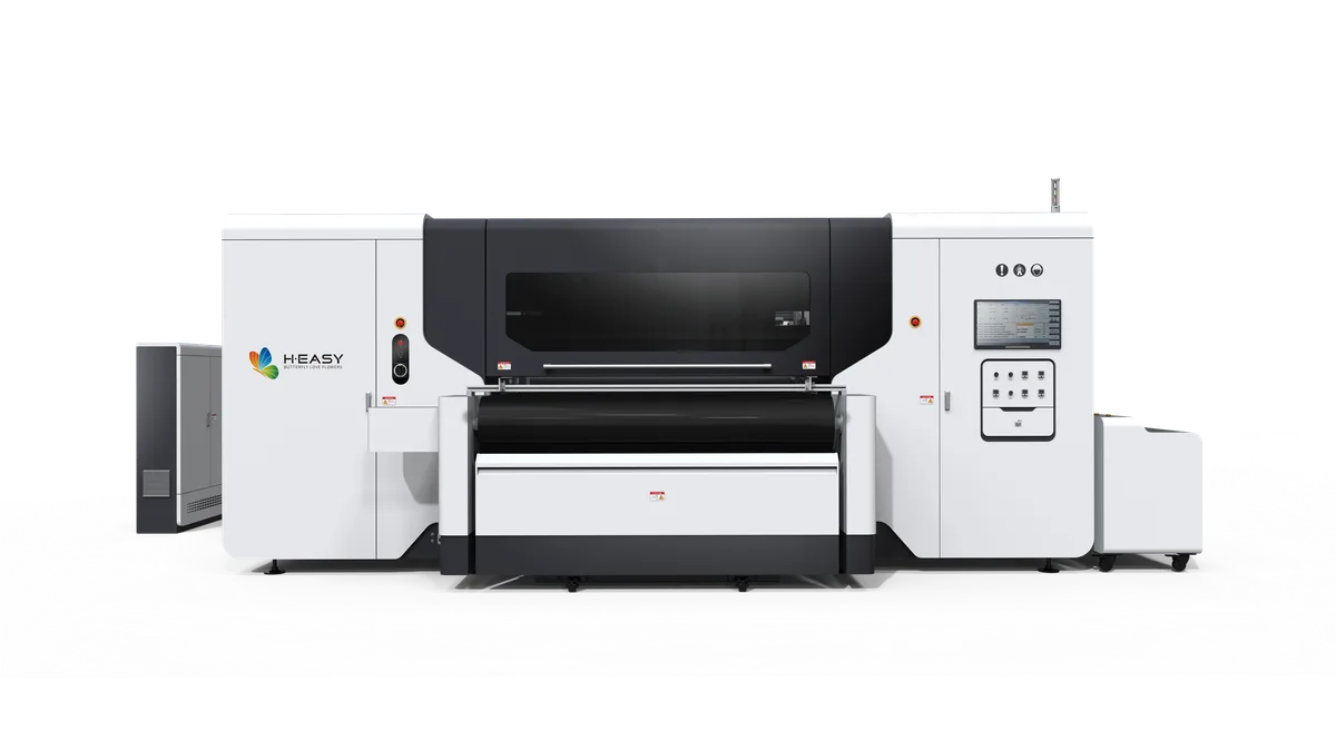
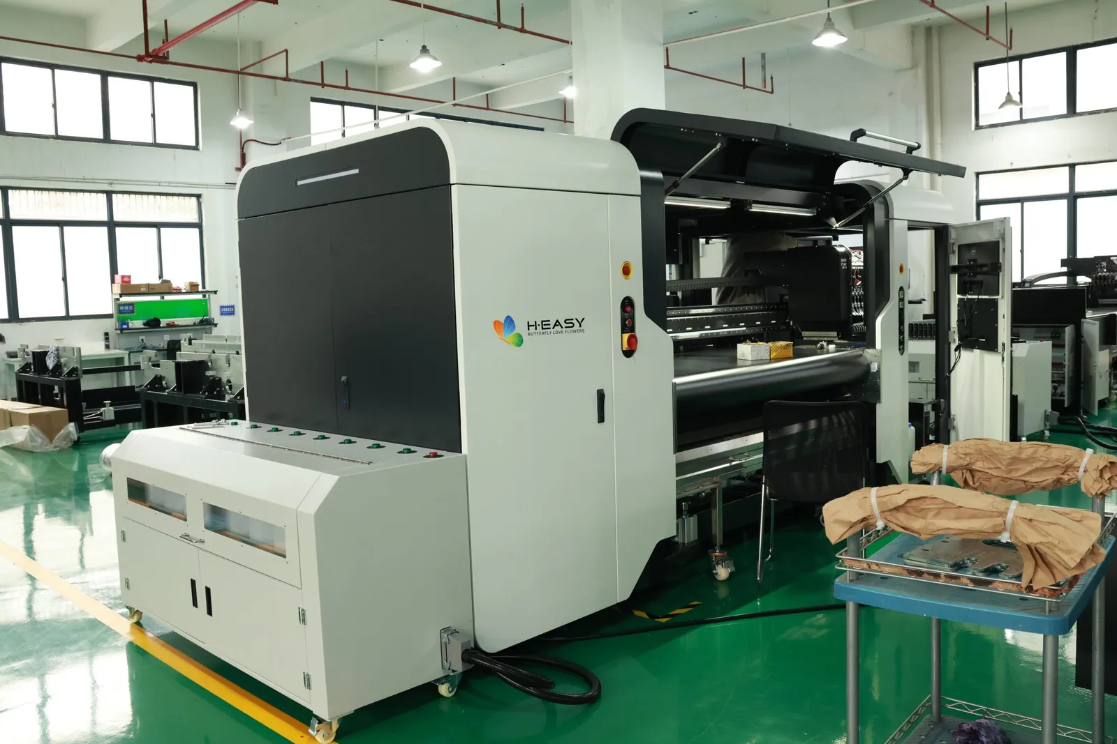
The R2R ink workflow guide helps identify which preparation and finishing chain belongs to the selected fiber. The R2R textile printer range is the relevant equipment path when media handling, carriage stability, and service access are part of the diagnosis.
Use the contact form to share the fabric construction, ink route, test target, nozzle check, before-and-after edge photos, and the stage where the defect first appears. That evidence is more useful than increasing resolution until one sample happens to look better.