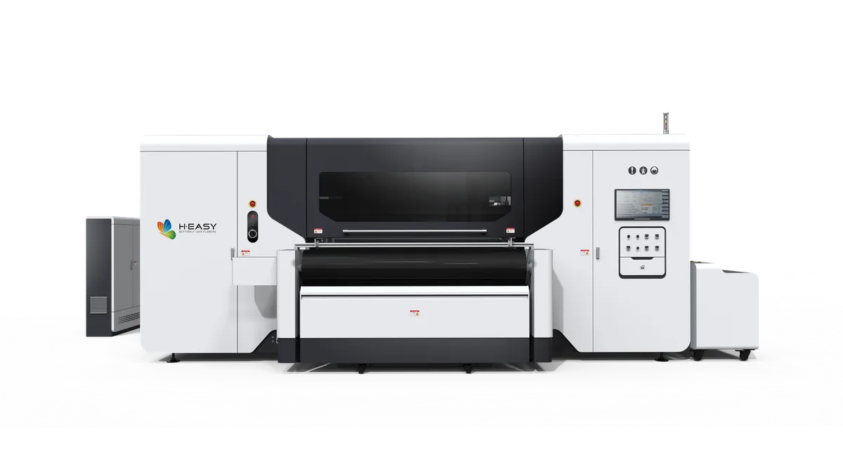
Digital Textile Printhead Installation Safety Guide
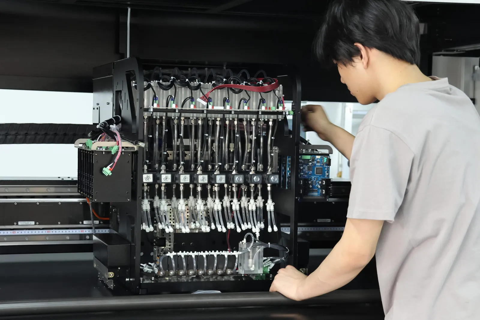
Prevent damage during digital textile printhead installation by treating the job as controlled electrical, fluid, and precision-mechanical service. Isolate the machine with the approved procedure, control static, confirm the exact part and cable orientation, keep connectors dry, protect the nozzle face, and use the documented priming and startup sequence before releasing production.
“Nozzle burnout” is often used for several different failures. An incomplete nozzle pattern can come from the cap, wiper, ink supply, contamination, trapped air, or an unsuitable operating state. A head that is not recognized can point to the head, a cable, connector, control board, or power problem. Replacing a part without separating those possibilities can damage the replacement or hide the original cause.
Confirm that replacement is the correct action
Preserve the fault evidence before opening the machine. Save the alarm text, nozzle pattern, affected channel, last known-good print, recent maintenance, ink-path observations, and any event such as a leak, strike, electrical trip, or connector work. Do not erase alarms or repeat aggressive recovery cycles merely to make the symptom disappear.
Use the model’s diagnostic flow to decide whether the fault is operator maintenance or service work. Inspect only the areas assigned to the operator. If there is liquid near electronics, visible heat damage, an electrical smell, an arc or shock, a damaged cable, an unknown connector position, or a required electrical measurement, stop and escalate to a qualified service person.
The R2R maintenance checklist shows how to compare the nozzle baseline, cap, wiper, ink supply, and recent changes before assuming the printhead has failed.
Prepare the correct service environment
The work area should be clean, stable, well lit, and arranged so that removed fasteners, covers, cables, and fluid parts stay identified. Lint, powder, loose fibres, packaging debris, and open fluid containers do not belong beside an exposed head or electronics bay.
Follow the printer and facility procedure for shutdown, energy isolation, and verification. Turning off a display or pressing the normal power button may not isolate every power supply, heater, motion circuit, stored charge, or external device. Do not reconnect power for a quick check while a connector is loose, a cover is open beyond the documented service state, or a person is still working in the carriage area.
Use the approved static-control method for the installed equipment. Keep the head in its protective packaging until the work area and printer are ready. Do not touch contacts, connector pins, or the nozzle face, and do not place the head on fabric, cardboard, foam, or an unknown plastic surface. Static damage may not leave a visible mark, so clean appearance alone is not proof of safe handling.
Verify compatibility before opening the package
Match the replacement to the printer configuration and service record, not to a similar-looking head. Confirm the approved part identity, revision, connector and cable set, mounting parts, ink chemistry, firmware or calibration prerequisites, and any single-use seals or fittings specified by the service procedure.
Inspect the replacement packaging for damage or contamination. Inspect the printer side for bent pins, discoloured contacts, cracked latches, strained cables, loose mounting hardware, ink residue, and fluid paths that could leak onto a connector. A damaged cable or wet connector is not corrected by fitting a new head.
If the old head failed after a strike, leak, cable change, board repair, or power event, resolve that initiating fault before installing the replacement. Otherwise the same condition can reach the new part as soon as the machine is energized.
Protect the electrical and fluid interfaces
Use the documented cable orientation and insertion method. A ribbon or plug that appears symmetrical may still have a defined contact side, seating depth, strain path, or latch position. Never force it, trim it, fold it sharply, or judge correct seating only by feel. Compare the finished connection with the service reference and check that no cable can rub on motion or be pulled by the carriage.
Electrical contacts must remain dry. Do not use ink, cleaning fluid, an unapproved solvent, compressed shop air, or a wet wipe on a connector. If fluid has reached electronics, isolate the machine and use the contamination-response procedure rather than guessing that evaporation made the assembly safe.
Ink fittings and dampers also have a model-specific orientation, seal, and support method. Do not twist tubing to make it reach, reuse a damaged seal, or leave a fitting under side load. Route the lines so carriage motion cannot pinch, stretch, or rub them, and contain any approved priming fluid away from the electrical side of the head.
Protect the nozzle face and carriage path
The nozzle plate is a precision surface. Do not rest the head on it, press it with a finger, scrape residue, or wipe it unless the exact procedure specifies the approved material, fluid, direction, and contact area. A clean-looking scratch or dent can still disturb jetting or sealing.
Before restoring motion, inspect the mounting, carriage clearance, cap and wiper position, fabric path, platen, and any height or alignment reference required by the model. Do not push the carriage by hand simply to see whether it feels smooth. Manual movement can be unsafe or can disturb a drive, encoder, lock, or service position unless the documentation explicitly permits it.
Also remove the cause of any earlier head contact. Raised seams, curled fabric, wrinkles, debris, incorrect loading, an unsuitable gap, or a misplaced service part can damage the replacement even when its electrical installation is correct.
Restore ink and power in the approved sequence
The order of fluid connection, priming, electrical verification, power-up, head recognition, alignment, and test printing varies by printer and ink system. Use the installed model’s procedure rather than a generic online sequence. Do not add ink near an unverified connector, dry-fire the head, or use production printing as a substitute for controlled priming.
At each documented hold point, inspect for leaks, abnormal pressure, cable movement, unexpected sound, alarm, heat, or smell. If the head is not recognized or an electrical alarm appears, isolate the machine again. Repeated power cycling or swapping cables under uncertainty can turn one fault into several damaged parts.
Once the approved startup checks pass, create a new nozzle baseline, complete the required alignment or calibration, and print a controlled reference sample. Compare the result by channel and defect location. The textile print-quality inspection checklist helps separate remaining jetting, placement, fabric, color, and finishing issues before normal production resumes.
Keep a replacement record that supports root-cause work
Record why the replacement was authorized, what was found on the old head, cables, connectors, fluid path, cap, and carriage, and what changed during the service. Attach the post-installation nozzle pattern, alignment evidence, reference print, alarms, and leak check to the printer history.
Do not discard the removed part until the service owner decides whether it is needed for inspection, warranty handling, or comparison. A recurring fault is easier to diagnose when the team can compare part identity, failure location, service action, ink-path condition, and the event that preceded each case.
Room condition and static can also influence installation and restart. Use the dry-weather maintenance guide when seasonal changes, dust attraction, fabric conditioning, or exposed ink residue may be part of the symptom.
For a model-specific installation boundary, compare the configured ink route, head and cable set, carriage design, commissioning record, and service scope with the current textile printer family. Use the contact form to provide the alarm evidence, nozzle pattern, part identity, fluid and connector observations, and actions already taken.